
Ubiquiti Smart Plug Teardown
My beloved Ubiquiti SmartPower Plug (USP-Plug-US) died about a year ago. Now that it’s out of production (and has almost no mention on Ubiquiti’s site), I took a stab at repairing it. Spoiler, I couldn’t fix it, but I still took some notes, in case they might be useful for other hardware hackers.
For the same $24 CAD I paid for the Ubiquiti smart plug, you could buy 3 or 4 from some obscure brand (with questionable software quality and security). While pricier, I bought the Ubiquiti one for 3 main reasons:
- Works locally, even when the internet is down
- Integrates with the Ubiquiti network controller
- Your Ubiquiti router can instruct it to restart your modem, when you internet lose connectivity for more than a few seconds
Getting in
… is a mess. With a combination of squeezing and prying, I’m fairly sure this is a one-way trip. I missed the memo to desolder the prongs before trying to pull the board out. I broke part of the PCB right off. Welp, it’s a salvage mission now.
Main board
I did my best to annotate the electrical connections. Pretty compact layout, but it’s pretty straight forward. A 3.3V power supply, a button, an LED, and a relay to energize the main relay.
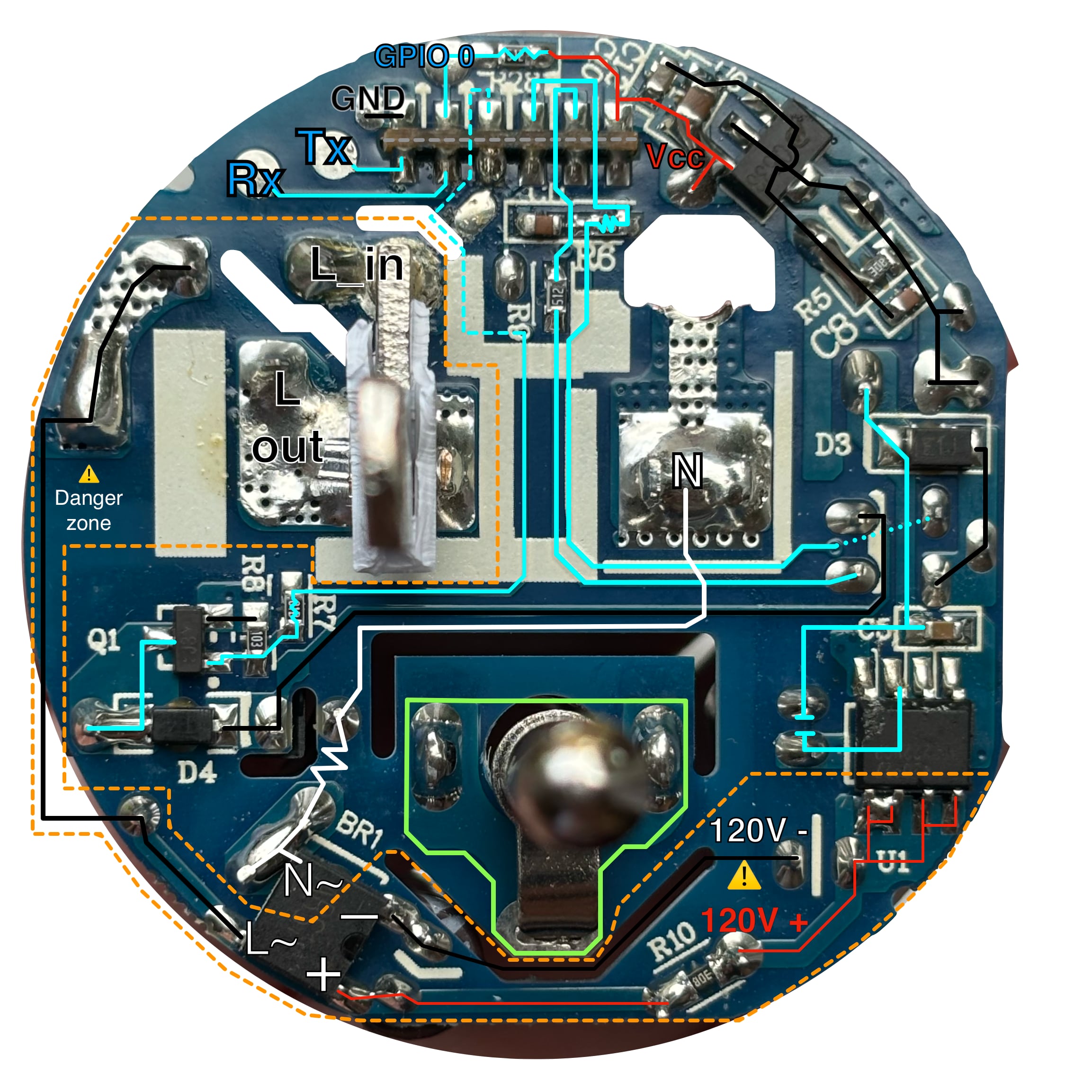
Connecting a programmer
You can connect a 3.3V UART programmer with these 5 easily accessible points:
- Rx: top-left-most test point
- Tx: the test point to the right of Rx
- V+: the big solder blob in the top-right, marked Vcc
- V-: the blob between Tx and GPIO 0, marked GND
To program the ESP8266 over UART, you need to boot it into serial bootloader mode. You do this by grounding GPIO 0 (the top test point) during start up.
Pinout
Here is the pinout of the edge connector of the the micro-controller board, that’s slotted into the main board photographed above.
It’s as accurate as I could get it, given my chip had a short across Vcc and ground. YMMV.
| Top - pin | 15 | 13 | 12 | 10 | ||
| Top - name | GPIO0 | GPIO15 | GPIO13 | GPIO12 | ||
| Top - function | GND | boot_sel | Relay | Button | LED | Vcc |
| Bottom - function | Tx | Rx | ? | ? | ? | ? |
| Bottom - name | GPIO1 | GPIO3 | ? | ? | ? | ? |
| Bottom - pin | 26 | 25 | 32 | 8 | 14/161 | ? |
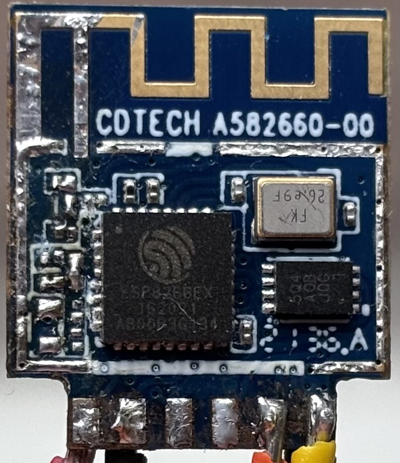
Micro-controller board
Since my plug was already toast, why not tear it down and see what’s under the grounding shield. Lo and behold, it’s a beloved ESP8266!
- An
ESP8266EXmicrocontroller (compatable with ESPHome!) - SPI Flash
- Marked:
5Q4 A0B J0G 1 - I think it’s a 16 Megabit
FM25Q16A-DN. Matches this product photo
- Marked:
- A 26 Mhz crystal oscillator (
FK 26.e9F)
Other resources
- ESP8266EX datasheet
- Common failure: Capacitor C3 replacement
- Another teardown with more photos: https://www.reddit.com/r/Ubiquiti/comments/1kuhjl3/usp_plug_open_and_repair_attempt/
-
This was electrically continuous with both pin 14 and 16. Not sure why. ↩